How much do you know about nylon 3D printing?

Nylon 3D-printed models are made of white, extremely fine powder particles with high strength and flexibility, which can withstand less impact force and slight bending.The surface of the model has a frosted, granular appearance with slight permeability.
1. Design specifications
2. Basic principles, Suggestions and strategies
1) Wall thickness
For 3D printing, wall thickness refers to the distance between one surface of the model and its corresponding surface.Wall thickness makes your wall either firm or flexible.A typical example of specifying a very small wall thickness is a spiral design, which requires certain damping properties and is designed to make it light and flexible.Increasing the wall thickness will have the opposite effect, which is more suitable for spiral vase design.
2) Model shell extraction
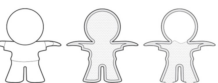
If possible, shell the model to avoid distortion and stains during printing.You can either just shell the model so that the sintered nylon powder is enclosed within the model.A small hole (two better) can also be designed to make it easy to pour out the unsintered powder after printing.
3) Large planes cause warping
Designing an A4 sheet of paper is a bad idea. Most of the time your model will be out of shape.This process is known as warping.Even if you add stiffeners to the bottom of the plane, it won’t solve this problem, it will even increase the probability of deformation.The key is to avoid large flat structures in the design.
4) Clearance between moving parts
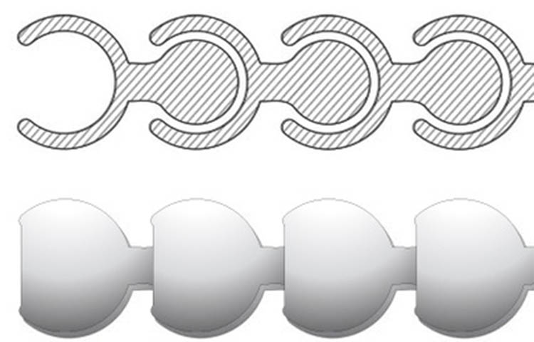
When you design an interlock structure like a pearl necklace, the gap between the surfaces of the product is critical, which affects the flexibility and bending properties of the product.We recommend that the minimum clearance on the model surface should be kept at 0.4mm, preferably if larger clearance can be allowed.
The more complex your design, the more difficult it is to get the powder out. Try to imagine how the powder flows through the product space.
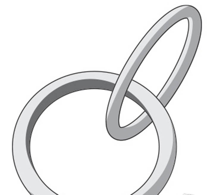
When designing necklace-like structures, make sure you leave enough space for the model.When the product is taken out of the printer, it allows the interring powder to flow out easily.
The space between the rings is guaranteed to be at least 0.4mm, which is better. The gap between the rings is closely related to the size of your design.For large rings you can leave a large gap and print more products in a limited space.For small rings, you have to limit the space to keep the horizontal and vertical distances between the rings.
5) Add texture to hide step pattern
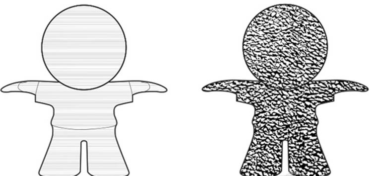
Due to the layered nature of 3D printing, visible step patterns often appear on the surface of products.To remove these steps, the model is usually polished.However, you can also add texture at design time to hide the step pattern.
6) assembly
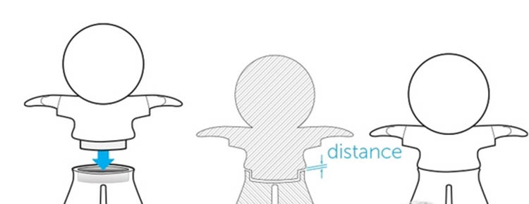
When designing the model to be assembled, it is important to keep enough clearance between the connected parts.Perfect assembly on software does not mean that the actual product does, because software does not take into account real-world friction.Therefore, keep at least 0.6mm distance between different parts.
7) Convex and concave details
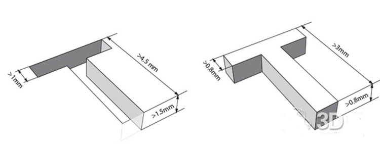
For concave text or surface details, we recommend at least 1mm in width, 1.5mm in depth, and at least 4.5mm in overall height.Raised text or surface details should be strong enough not to break during printing or transportation.We suggest that the text line width should be at least 0.8mm, the overall height should be at least 3mm, and the raised height should be at least 0.8mm.
3. Basic principles, Suggestions and strategies of nylon polishing
Grinding (also called machine grinding) is a special post-treatment process for nylon products.To obtain a smooth surface, the model is placed into a drum fitted with small stones. The drum performs high-frequency vibration to polish the product.
1) Only the high strength parts can remain intact
A variety of factors can lead to unpredictable polishing results.One reason is the geometry of the model, which can be different every time you put it into the device.In general, you should ensure that all walls are not less than 1mm thick.Although we carefully lay out the model before printing and try to make the wall model appear weak when printing layer by layer, it is still possible that some structures of your model will be more sensitive to polishing than others.Therefore, we suggest adding as much “extra thickness” to the wall surface as the design allows.Polishing is not recommended for models with fine features such as small columns, which can be easily damaged during polishing.
2) Internal surface polishing
As mentioned earlier, small stones are used to polish the surface of the model.However, due to the size of the stone, they can easily get stuck in the small inner hole of the product.Since we recommend that all holes to be polished should be larger than 6.5mm in diameter, it helps to avoid the appearance of rock holes.Also note that the inner surface of the model is always less polished than the outer surface.In fact, if the hole is less than 6.5mm, the inner surface of the model won’t be polished, because the stone can’t get inside the model.
3) round edge
If your model contains sharp edges, it will be rounded.Smooth transition areas of rounded corners and faces are more polished than sharp edges.
4) Convex and concave details
Convex details on the model tend to be polished off by stone. Make sure the convex height of these details is over 1mm, otherwise they may disappear when polished.The details are less problematic because most of the time the stone cannot get into the groove, but the edges can still be affected.For safety reasons, ensure that the depth of the groove is greater than 1mm.
4. Basic principles, Suggestions and strategies of nylon components
A 3D model file can have multiple independent shells.If the housing is an interlock part similar to a chain mail, refer to “Clearance Settings for moving parts” above.If the product is not interlocked or intersecting, there are some additional principles to follow.
1) Where are the parts?
If a model file has many non-interlocking or connected shells, it will bring a lot of trouble to the production staff.First, it can be difficult to identify all the parts or shells.When producing your product, your parts will be mixed with other orders in the printer.Most printers have a fixed processing area.In order to save time and cost, we will try to fill as many parts as the equipment allows.This virtual 3d placement will be used for 3D printing.When the product is finished, we get a powder block filled with the parts.If it contains multiple small, disconnected shells, you will discover how painful it is to identify all the small parts from the powder.Therefore, in order to solve this problem, we only accept parts that are either connected or encapsulated in containers.Read on for more details and the importance of these operations.
2) Connect the parts
One way to ensure that all the shells you design stay together and can be treated as a part is to connect all the shells with support beams.It is important that all parts are well connected and that the support beams are strong enough.Ensure that the minimum wall thickness of the beam is not less than 3mm, which may not be strong enough to support the various parts of your design.
The heavier the individual parts, the thicker the connecting beam.If the connection structure of the part is too weak, you risk losing the part.To reduce the weight, the heavy parts can be removed from the shell.Don’t forget to punch a few holes to make sure the powder inside the parts can be poured out, otherwise the parts won’t lose too much weight.The wall thickness of the parts shall be less than 5mm after shell extraction.
It is recommended that each housing have 4 sturdy connection structures.The larger the shell is, the more difficult it is to properly connect the shell, which is also the reason why the sum of the dimensions in the three directions of the design model (X+Y+Z) is less than 350mm.
3) The parts are strung on the ring
If your parts have through holes, another way to connect them is to string them on a ring.Attach your parts to a chain-shaped closure ring to ensure that we can treat all the parts as a whole.However, once the parts are grouped in this way, we cannot position them individually or adjust the space between the parts.To avoid problems in the machining process, reserve at least 1mm clearance for each part.The minimum thickness of the ring shall not be less than 3mm.Control the number of parts on the ring, many large and heavy parts are more likely to break the ring.Designs with a high risk of ring failure are not allowed.
4) Fully enclosed box
The final solution is to design a closed box around your parts.Since there are no holes in the box, all the powder will remain in the box.Remember to add unique tags like the design file name to the box so we can easily find your parts.Use an easy-to-read font like Arial Black to carve markup text.We recommend at least 1mm in line width, 8mm in depth, and at least 3mm in overall height.
For the wall surface of the sintering box, the thickness shall be at least 1.2mm.Note that at the end you need to cut open the sintering box and take out the parts. The thicker the wall, the more difficult it is.
In addition to the characteristics of the sintering box, the spacing between the parts inside the box and the inner wall of the sintering box should be greater than 3mm.If the distance is less than this, the parts may be sintered together.
If the overall volume of the sintering box is greater than 1700cm3, you should pay attention to the density of the parts inside the box.Too high component density will lead to abnormal cooling, which may cause yellowing or deformation of the product.The total volume of the model is limited to less than 10% of the volume of the sintering box.
Keep in mind that you will need to clean up any excess powder at the end and have a work area ready to accept some dust, otherwise use the other methods above.
We also suggest that the box body be designed to facilitate the opening area, which can be achieved through the opening, such as a 0.8×2mm rectangular hole.
5) Grid box body
Another way to allow you to print multiple shells at once is to put all the parts into a box, which means you need to design a container that wraps all the parts.There are some basic principles you should follow when designing a fit.Remember to add unique tags like the design file name to the box so we can easily find your parts.Use an easy-to-read font like Arial Black to carve markup text.We recommend at least 1mm in line width, 8mm in depth, and at least 3mm in overall height.
Perforated boxes are recommended, which allow us to remove excess powder from the parts.Here is the minimum characteristic size of the sintering box: the minimum wall thickness of the grid line is 1.2mm, the minimum mesh size is 4x4mm, and the maximum mesh size is 15x15mm.Make sure that the parts in the box do not pass through the perforation and that the parts used are inside the sintering box.Parts that pass through holes may be lost.
In addition to the characteristics of the sintering box, the spacing between the parts inside the box and the inner wall of the sintering box should be greater than 3mm.If the distance is less than this, the parts may be sintered together.
If the overall volume of the sintering box is greater than 1700cm3, you should pay attention to the density of the parts inside the box.Too high component density will lead to abnormal cooling, which may cause yellowing or deformation of the product.The total volume of the model is limited to less than 10% of the volume of the sintering box.
If there are fragile parts in the box, we suggest connecting these parts to the housing, which can prevent the fragile parts from hitting each other during transportation.Otherwise, handling the parts during transportation will cause the parts in the box to loose and destroy each other.
6) the results
Once printed, the remaining powder is removed from each model by brushing or sandblasting.This is also necessary for grouped models, but in this case it is more difficult to clean up each part.Because the parts are connected to each other or to the sintering box, not all edges and corners can be handled.Please note that a small amount of powder may be left in the product upon receipt of the goods.To further clean the model, use a brush or compressed air.
Note that the grouped model provides only natural processing.Due to the limitations of such models described above, good results are not guaranteed.Other post-processing processes can also be used, but require very clean and accessible parts, which is not appropriate for the in-box grouping model.
5. Basic principles, Suggestions and strategies of model flocking
Unlike model painting, some treatments change not only the look of the product, but also its touch.When the model is flocking, the appropriate adhesive is applied to the product surface.The fabric then penetrates the adhesive surface to produce the desired velvet effect.
1) the flocking
The process of adding velvet effect to the model surface is called flocking, and electrostatic flocking equipment is used.First, apply the appropriate adhesive to the surface of the product.The metal needle is then connected to the surface of the model and earthed.A negative potential is obtained by flocking with a flocking machine. The velvet material flies vertically to the substrate and adheres to the previously applied adhesive.There will always be a mark somewhere in the model, because the grounding pin needs to be inserted.Therefore, we expect to have metal pinholes with a diameter of 1.6mm and a depth of 2mm. It is recommended to select the location of the cloth needle in the invisible part of the model (such as the bottom).
2) Sharp angles and details
Because flocking sticks the fiber to the surface of the model, the details of the product are less crisp.The binder will be sprayed on the surface of the model, less glue will cover the hard-to-reach areas, and there will be less velvet in these areas.Therefore, if flocking is to be used, avoid design with sharp corners or internal structural models (such as vases).Very small parts (such as small features, hinged edges, frames, etc.) are also difficult to cover fibers because the flocking area is limited.


