
Blog
Detection and quality control of 3D printed metal products: Micro CT

Micro CT detection (X-ray CT) is one of the detection methods for 3D-printed metal products. Other methods include eddy current detection, ultrasonic detection, white light interference detection, and non-related optical detection.However, given the latest advances in various technologies, Micro CT has the most potential for nondestructive testing of complex internal structures and geometric shapes.The following is a description of Micro CT capabilities.

Figure 1. Nikon XT H225 ST MODEL CT system
Micro CT (X-ray CT) is the only method that can effectively realize the nondestructive measurement of internal body defects and complex geometric shapes of parts.Eddy current testing can only detect defects near the surface area of a part.Ultrasonic testing is suitable for simple geometry near the surface, and the inner region that can be measured is relatively limited.Optical and interference techniques can only detect the surface characteristics of a part.Although interferometry is much higher (up to a few nanometers), Micro CT scans the internal and external surfaces of a part at a time with resolutions up to and sometimes below the micron level (hundreds of nanometers).
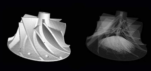
FIG. 2 CT scan can detect external and internal features
With the increasing impact of 3D printing on the manufacturing industry, people are increasingly interested in Micro CT.Global spending on 3D printers, both desktop and industrial, reached $11 billion in 2015 and is expected to reach $27 billion in 2019, according to the consultancy.Marketsand Markets, another firm, predicts that 3D printing will grow at a compound annual rate of 30% and reach a market size of $30 billion by 2022.According to an April 2016 study, the firm Price Waterhouse Coopers (PWC) said 3D printing was entering a new era in U.S. manufacturing.Compared with two years ago, more manufacturers (52% this year and 38% in 2014) expect 3D printing to be used in large-scale industrial production in the next three to five years.
More and more users are considering 3D printing to reduce the weight of metal parts without reducing their strength, such as aviation products, which can help improve efficiency.In aviation, automotive, energy, and medical fields, where safety is critical, it is necessary to determine whether there are voids and inclusions in products, their size (individual and whole), and where they occur.In addition, it is also critical to determine whether the size of the product deviates from the design.
X-ray CT is a very powerful tool for this type of problem.By providing a full three-dimensional density map of the sample, Micro CT provides all relevant information in an easy-to-read, visual manner.
Welds need to be tested. What about 3D printing?
For the traditional welding process, everyone will always do the quality inspection of its products.For metal 3D printing, the product is essentially a large solder joint.Therefore, if it does not carry on the void, the inclusion, the accuracy detection, that is completely unreasonable.The physical and chemical process of metal 3D printing is very complex, and various risks arise, such as loose and incomplete melting powder in the molding bin, as well as random distribution of the location and characteristics of defects.
With traditional processes, a few X-ray photographs in a specific direction can determine the product condition.However, for 3D printing characterized by layer by layer accumulation, the whole part needs to be tested.When testing the structural integrity of these parts, the following questions are the first concerns:
1) Residual powder clogs the channel;
2) Defects (voids and inclusions) — pores, pollution, cracks;
3) Dimensional deviation from CAD model — dimensional analysis, wall thickness measurement and deformation.

Figure 3 CT scan shows an internal blocking passage without damaging the part
For example, a mold is made using the SLM process.Micro CT can determine the morphology of the 3D-printed internal flow passage, and its accuracy can be as high as 5-10 microns according to needs.Through flow and cooling process simulation, it can be determined that the accuracy is sufficient to meet the requirements.
For example, a mold is made using the SLM process.Micro CT can determine the morphology of the 3D-printed internal flow passage, and its accuracy can be as high as 5-10 microns according to needs.Through flow and cooling process simulation, it can be determined that the accuracy is sufficient to meet the requirements.
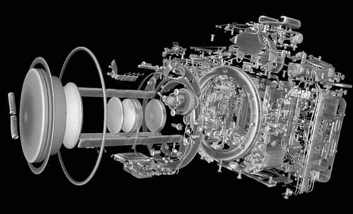
The size of the specimen that can be scanned by CT is related to the material, the energy of the X-ray source (usually in kV).Large size, low energy density samples can be scanned, small size, high energy density samples can also be scanned.Typical maximum sample scanning size includes:
1) 225kV — aluminum alloy piston head, diesel engine fuel injection nozzle;
2) 450kV — aluminum alloy cylinder cover, aircraft turbine blade.
The maximum size of the part is also limited by the size of the detector and is also related to X-ray penetration.It decreases as the density and atomic number of the material increase.Polymer materials pass through more easily than steel, and steel passes through more easily than tungsten.
CT scan case study
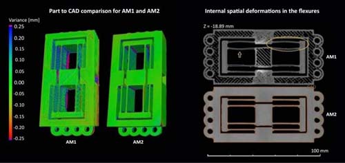
A CT scan study of 3D printed flexible structures shows the machining capabilities of both processes.Although the research is focused on polymer products, the same principles and advantages apply to metal 3D printing.The first flexible sample was processed by FDM process, and the second sample was printed by SLA process.In general, the printing resolution of FDM and SLA processes are 100 microns and 0.5 microns respectively.
Micro CT scan showed the deviation of the two sample sizes relative to the original CAD model.It can be seen from the test results that the deviation from the CAD model can be as high as ±0.25mm, and the deviation of sample 1 is larger.Correspondingly, the deviation between sample 2 and THE CAD model was mostly ±0.1mm, with exceptions at the edge or sharp Angle of the sample surface.In addition to external testing, the cross section of sample 1 shows the internal residual deformation.On the contrary, the thin-walled flexible structure of sample 2 did not show obvious deformation.
Rules of Micro CT and breaking conditions
High-precision Micro CT technology has been continuously developed in the past ten years, and its applications are widely used in automotive, aerospace, energy, medical and consumer products, as well as metal, plastic and other workpiece materials.The supporting software tools make it possible to refer to and analyze parts relative to CAD models, either directly from the solid to the CAD model, or through geometric dimensions and deviated profiles.As the cost of the technology is reduced to a sufficiently low level, Micro CT is more competitive with other technologies and will be used in a wider range of faceface applications.
A better understanding of the application principles of Micro CT not only helps to reduce production costs and improve production efficiency, but also helps to understand when relevant principles can be broken to further improve its application flexibility.The correct usage rules of Micro CT are as follows:
1) Transmit samples from different angles;
2) Minimize noise points on each projected image;
3) Use filters to reduce beam hardening;
4) 360° rotation is often used;
5) Use the full dynamic range of the detector;
6) Keep the object in view.
X ray basis
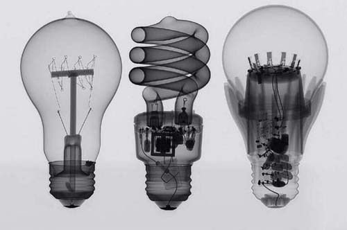
X-rays are at the short end of the electromagnetic spectrum, and their average wavelength ranges from 10-8 meters to 10-12 meters, roughly the size of a water molecule.Micro CT does not use a radio wave source. Instead, it produces electrons from a hot filament similar to a light bulb and accelerates through high voltage at a speed up to 80% of the speed of light.The electron beam is focused into spots of 1-5 microns in diameter by a magnetic lens and hits a metal target. The sudden deceleration of the electrons generates more than 99% heat and less than 1% X-rays.
When electrons bombard a target, X-rays are produced by two atomic mechanisms:
1) Under the condition that the electron energy is high enough, the inner orbital electrons of metal atoms can be knocked out. The transition process of high-energy electrons to low-energy ones will produce X rays.This process produces a small number of x-rays with discrete frequencies, sometimes called characteristic radiation lines.
2) Toughening radiation: Electrons are scattered by the strong electromagnetic field close to atoms with high proton number, accompanied by the generation of X-ray.This type of X-ray has a continuous spectrum, and the intensity of the X-ray increases with the decrease of its frequency.
The X-ray travels in a straight line through the object being detected and hits the detector.Objects absorb some of the X-rays (denser objects absorb more), and the rest reaches the detector.When the X-ray energy is low (less than 60kV), the absorption difference along the X-ray motion path to the detector is detected and shown in the form of a shadow map.When the X-ray energy is relatively high (60-225kV), both absorption and scattering occur, which reduces the contrast of the image.When the X-ray energy is higher than 225kV, the scattering is detected by the linear detector, although the image production efficiency is reduced.When the energy exceeds 300-400kV, scattering becomes the main contrast mechanism.In other words, more of the X-rays are scattered than absorbed.
The amorphous silicon flat-panel detector has an LCD screen that converts X-ray energy into light and images on a photosensitive diode array. Electronics allow the image to be read by a computer.These tablets have a wide range of pixels and are sensitive up to 16 bits (64K grayscale level).
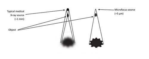
The sensitivity of the detector depends on the size of the part and the X-ray source.A large number of typical high-energy X-ray sources are millimeter focused, with a size of about 1mm, which limits the resolution of the image relative to the detector.Getting high resolution requires very small detectors, and geometric magnification is not possible.Micron focus means that X-ray sources are only a few microns or so in size, and standard medical detectors can be used to improve image resolution using geometric magnification.
Micro CT overview
Combining the power of X-ray penetration with the increasingly powerful data-processing capabilities of computers, computed tomography (CT) has become a reality.The basic apparatus consists of an X-ray source, an object under test, and a detector.The object rotation platform guarantees the implementation of rules 1, 4, and 6 mentioned above.
A sample can produce thousands of photographs.According to certain algorithms, the 2d pixels of each 2d image will be converted into voxels during 3d reconstruction.For example, there are 3,000 images, and each 3D voxel is processed 3,000 times.The result is a three-dimensional volumetric map of the object, with each voxel having its own coordinates and density.The user will not only get the information of the inside and outside surface of the sample, but also the density distribution inside the product.In addition, software can be used to look at sections of the product to gain more information without damaging the product itself.
Image intensity is the basis of sample measurement.In CT, we measure the linear decay of x-rays, or the amount of x-rays absorbed per unit length of material.Unfortunately, defects or artifacts can show up in CT data and affect test results.On a lamellar picture, the noise looks like a stain, but it can be mitigated by increasing the amount of X-rays.
There will also be nonlinear detector noise points on the projection diagram, which are generally located in the same position of all projection diagrams.During imaging, this noise is reconstructed as a ring, or annular artifact.The noise on the reference graph has the greatest effect on the pseudo-work because it is used repeatedly to correct each projection and the negative effects are magnified.The noise in the black area is more influential than the white area, because the signal in the black area is weaker and the signal-to-noise ratio in the black area is smaller.
The ring artifact near the axis of rotation is stronger because there are fewer pixels in this area.In the collection of black and white reference images, the effect can be weakened by averaging over multiple images.
Beam hardening is the self-filtering of x-rays by the sample, in which case the energy inside the sample is higher and the penetration ability is stronger.For this reason, the linear attenuation of X-rays inside the sample will be lower than the edge, which will further lead to the intensification of beam hardening.
Prefiltering x-rays can weaken the beam hardening, and some beam hardening correction can also be performed in CT software, which is the best application for single-material samples.
As stated in Rule 5, it is important to use the full dynamic range of the detector, and the high dynamic range detector helps detect small signal strength differences.
Striation artifacts are caused by beam hardening or poor X-ray penetration in the sample.Lack of penetration can be addressed by increasing X-ray intensity unless you have used maximum energy intensity.
Striated artifacts can be filtered by the beam or by using a high dynamic range detector to mitigate the impact.The scattered radiation can be reduced by aligning the X-ray beam with the detector and detecting only those rays that travel in a straight line from the source to the detector.
Following these rules will make CT results as good as possible and, in most cases, very good.However, if you need qualitative information, or if the information you need is not affected by artifacts, you can break these rules.
Rule 1: Transmit samples from different angles;Rule 6: Keep the object in view
If the material outside the field of view is more uniform and regular in shape, there will only be some small rings at the edges, and the internal features will be easily observed.In this case we can zoom in on the inner observation area to get more information.If the analysis feature is close to the center of the sample or the feature size is much larger than a single pixel, the number of projection can be reduced to improve the scanning speed.
Rule 2: Minimize noise on each projected image
If the time is limited, reducing the noise of the black and white reference graph will reduce the overall number of noise points, but not significantly extend the whole scanning time.
Rule 5: Use the full dynamic range of the detector
Very low intensity X-rays are often used to improve contrast when testing low-density samples.Full motion means long exposure times, and cutting the exposure time in half will lose very little information, but save a lot of time.
conclusion
Micro CT usage rules are based on CT reconstruction theory, and adherence to these rules means that the highest quality CT data is very likely to be obtained.However, sometimes breaking these rules can save a lot of time without significantly sacrificing image quality.
Micro CT scans are now much faster and more suitable for production line applications.In addition, the loading and unloading process of scanning similar parts can be automated, making it possible to reduce the scanning time of individual parts to tens of seconds.Users can obtain:
1) Better observe the interior of metal 3D printed parts;
2) Faster optimization of product prototype and production process;
3) Quality control — more confidence in incoming and outgoing products;
4) Reduce losses by avoiding destructive tests.
As 3D printing continues to rewrite the rules of the game in manufacturing, X-ray CT can be a powerful assistant, identifying geometric deviations and internal defects in products through nondestructive testing.


